
In our next Li-ion Battery 101 blog, we'll discuss the brain of a lithium-ion battery pack: The Battery Management System (BMS). We briefly touched on the BMS in a recent post, "The Construction of the Li-ion Battery Pack," but let's get a better understanding of what exactly the BMS does.
The primary purpose of the BMS is to protect the cells from operating in unsafe conditions. In addition, the BMS can also be used to report status (i.e. battery life) to the user and/or powered (host) device while keeping track of any anomalies with the battery. A Battery Management System (BMS) typically includes:
Primary Protection Circuit- Critical feature of the BMS
- Protects from unsafe conditions like over current, over/under voltage, and over/under temperature
- Performed through analog monitoring IC that can monitor temperatures, current, and voltage levels of cells/cell stack
- Redundant protection primarily from overvoltage, can be added for overcurrent and over temperature
- Typically done via chemical fuse; will permanently disable the battery pack
- Digital Monitoring IC which can provide feedback on battery capacity
- Three common techniques for determining capacity left on cells includes:
- Voltage Sense – Most Primitive
- Columb Counting – Measures capacity used and subtracts from known full capacity
- Impedance Tracking – Calculates the capacity based on the impedance of cell
- Cell imbalance can shorten battery life
- Caused by uneven current draws, uneven heat loading, poor cell matching
- Cell balancing circuit tries to equalize the cell charge to keep all cells connected in series at the same level
Figure 1 is of a block diagram illustrating a typical Battery Management System. As battery packs increase in size and complexity and the end user / host device needs are more robust from a monitoring and communication aspect, the BMS will also need to be more complex. For the purpose of this discussion, we are focusing more on a basic explanation of a BMS.
Figure 1
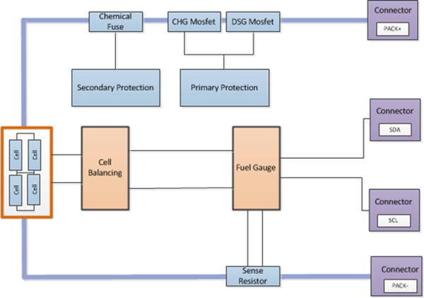 A BMS can protect a battery pack or host device from a variety of events depending on what hardware is selected or required for a particular application. For example, it can protect from undesirable current (A), voltage (V), and temperature (C) events. The BMS keeps track of any anomalies with the battery, such as what protections have been activated and how much power/capacity is remaining when a battery is charged or discharged. They can also help with cell balancing, along with other cell maintenance and optimization features.
A BMS can also have Secondary Protection Circuits which are hardware-based to back up the primary circuits if those were to fail. A BMS may include the ability to regulate the output and input of a circuit using Buck, Boost, and Low-dropout Regulators (LDOs) which can help an end device maintain the power it needs to function correctly. While these devices can have one input/output for pack voltage, they can also have multiple power options with the help of a Hot Swaps or Ideal Diodes.
A BMS detects current, voltage, and temperature events by using either an Analog to Digital (A/D) converter, a comparator, and a sense resistor/shunt. Using A/D or comparator circuits in conjunction with a sense resistor/shunt, allows a BMS to detect how much current is flowing in or out of the battery, protecting the cells from being charged or discharged too quickly. Voltage is measured using A/D or a comparator to determine the potential difference between two points. For example, the top and bottom of a cell or cell stack to protect a cell from being over-discharge, overcharged, or becoming imbalanced from other cells in series.
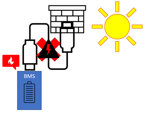
Temperature is measured using A/D or a comparator and measures the resistance across an NTC thermistor to protect the cells from being charged/discharged at dangerous temperatures. An example of how this works is depicted in Figure 2. Note how the additional heat from the sun activates the BMS so that the battery does not overcharge.
Figure 2
A BMS can be an incredibly configurable system with the ability to communicate with the outside world using SMBus, CAN, HDQ, I2C, and other communication variants. These systems can be tuned for use with certain cells or any cell depending on the algorithms that are created/used. When figuring out how much capacity is remaining, some algorithms just use voltage which is called CEDV, some use current, and others use both which is the measure of impedance. But the best BMS configuration is one that uses voltage, current, and temperature to make a more holistic view of the system. For example, environmental and consumption factors will give better predictability when it comes to remaining capacity/power within the batteries.
Overall, the BMS provides the safety and protection required to keep Li-ion battery packs safe while also enabling intelligence/smart features for communication with the end user and/or host device as well a live reporting of battery health. It is for these reasons why it is so important to work with experienced battery manufacturers who are trusted to build reliable Battery Management Systems. At Inventus Power, our battery packs and battery management systems are designed in-house and are tested and certified to industry standards. In our final Li-ion Battery 101 blog, we'll explore the major battery regulations we follow to keep our batteries safe.
Written by: Chris Reinke, Electrical Engineer II, Inventus Power